Hill Climb Model Car Project
Post-Race Retrospective: 0° to 50° Gradient Negotiation, 24:1 Worm Reduction, Empirical Logging & Drivetrain Optimization
Final Vehicle Architecture: Concept 3
Designed to conquer extreme ramp gradients up to 50° under tight kit and single-motor electrical constraints. Concept 3 traded top speed for extreme mechanical advantage, 4-wheel drive contact patch distribution, and rigid chassis anti-flex bracing.
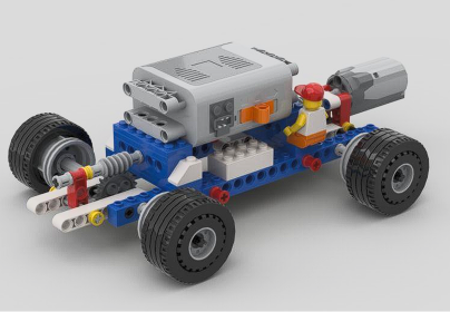
Render showing the longitudinal central driveshaft, front and rear 24:1 worm gear reductions, lowered battery box, and structural longitudinal cross-bracing.
Engineering Specifications
- Drive Layout: All-Wheel Drive (AWD) distributing tractive effort across four tire contact patches to prevent single-axle wheel slippage on steep angles.
- Gearing Strategy: 24:1 worm gear reduction maximizing torque multiplication and acting as an inherent mechanical anti-rollback brake on steep inclines.
- Packaging & CG: Flat central battery placement and low-slung ballast below the motor to suppress front-axle pitch-back rotation on 40°–50° ramps.
- Structural Anti-Flex: Locked gear center-to-center geometry with boxed cross-bracing to prevent high torque separation under extreme ramp resistance.
- Vehicle Dimensions & Mass: 24.5 × 13.8 × 7.3 cm • 252 g dry mass / 437 g race trim mass.
Applied Physics & Free-Body Model
Mathematical modeling of downhill gravitational forces, normal load shifts, and motor power curves that governed the engineering transition from speed to torque.
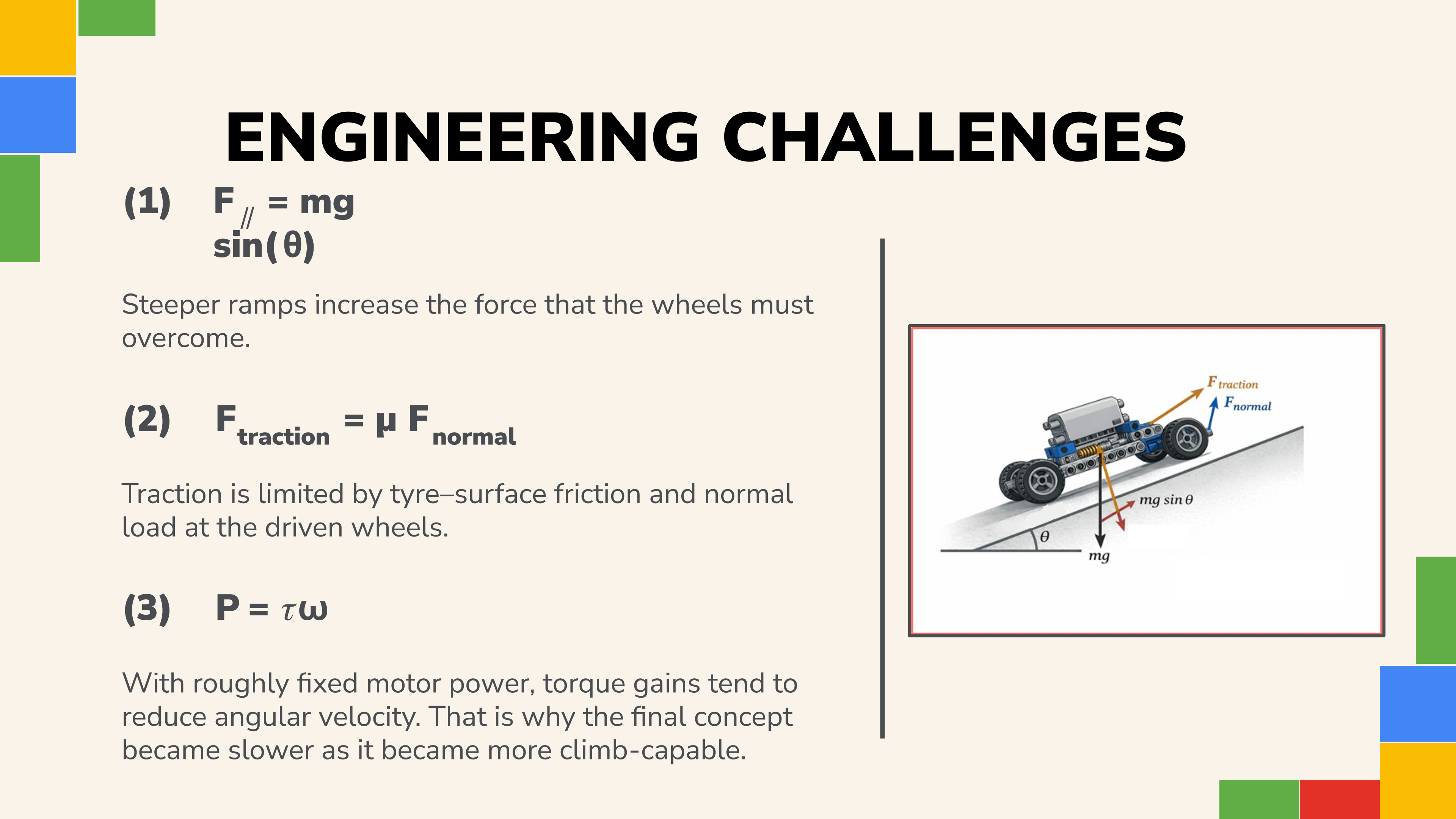
Vector resolution of tractive force, normal reaction force, and down-slope gravitational component as ramp angle θ increases from 0° to 50°.
Core Governing Equations
Data-Driven Concept Evolution
Systematic engineering progression testing 3 distinct drivetrain layouts against ramp angle thresholds, converting empirical failure points into architectural upgrades.
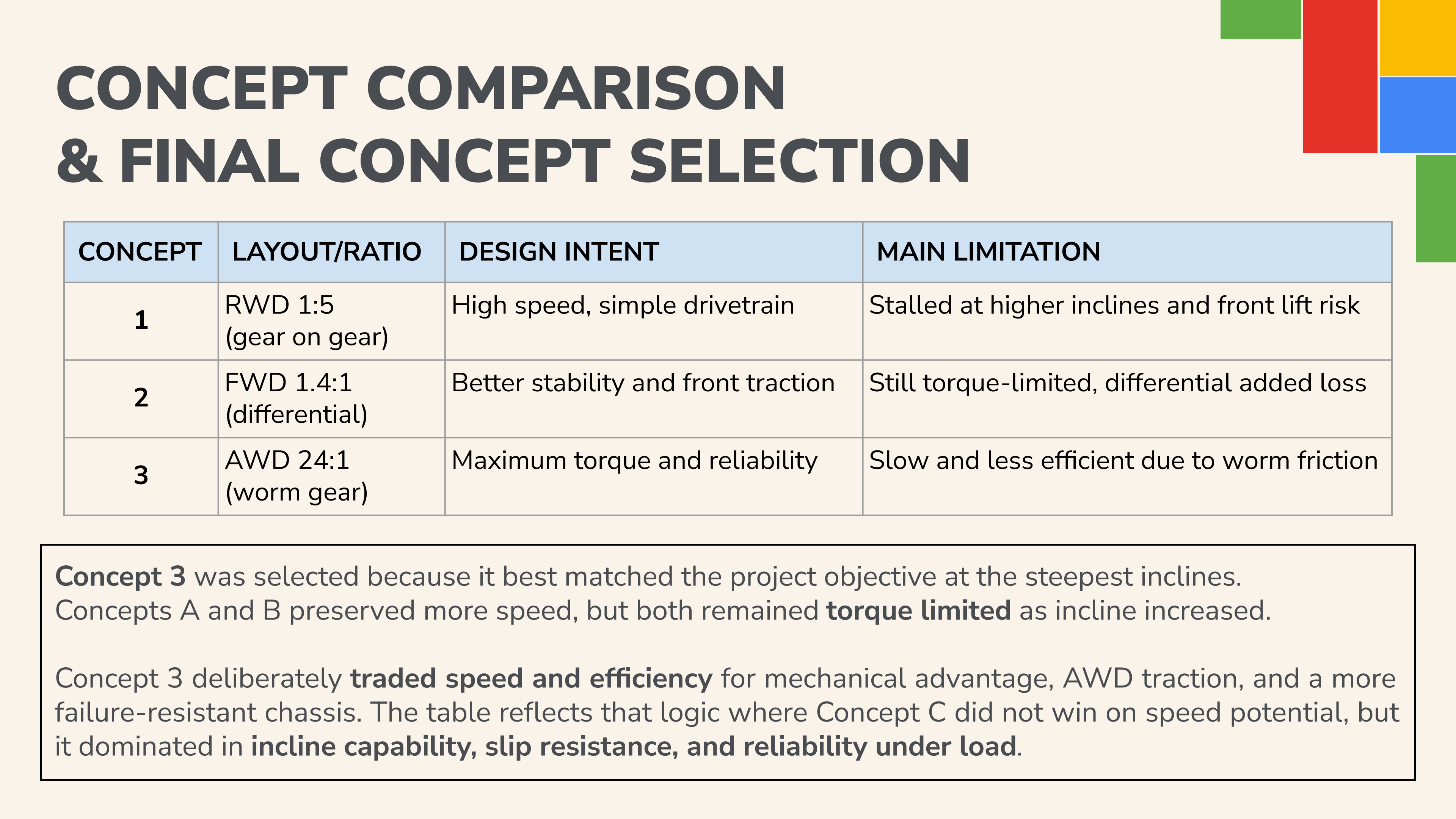
Direct comparison between high-speed RWD 1:5, stability-biased FWD 1.4:1 with differential, and the ultimate AWD 24:1 worm drive configuration.
Drivetrain Performance Comparison
| Concept | Layout & Ratio | Design Philosophy | Test Evidence & Outcome | Decision & Next Step |
|---|---|---|---|---|
| Concept 1 | RWD 1:5 (Gear-on-Gear) | Pure speed on flat ground with low center of gravity | Fast on flat (1.745s average), but motor completely stalled at 10° ramp | Abandoned speed bias; recognized wheel torque as true limiting bottleneck |
| Concept 2 | FWD 1.4:1 (Differential) | Front-wheel traction & central battery balance | Climbed 10° (4.27s), 20° (4.06s), 30° (4.36s), but stalled at 40° | Proved traction was improved, but single-axle torque was still insufficient |
| Concept 3 (Race) | AWD 24:1 (Worm Reduction) | Maximum torque multiplication & anti-rollback stability | Completed all runs from 0° to 50°; 100% reliability under extreme load | Selected for official race; validated torque-for-speed trade-off |
Official Race Event Performance Analysis
Quantitative retrospective comparing official race run times against incline angles, confirming 100% completion success across all prescribed ramps from 0° to 50°.
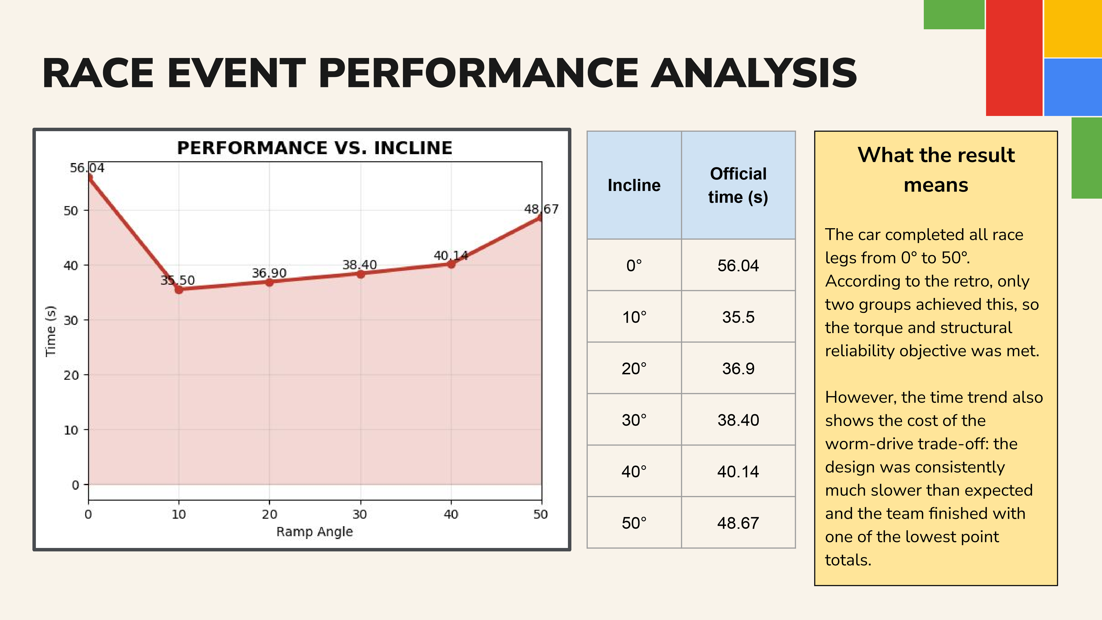
Time vs. ramp angle plot demonstrating consistent, stall-free climbs up to 48.67s at 50°. Only 2 teams in the entire cohort accomplished this feat.
Official Race Telemetry
- Reliability Objective Met: Avoided motor stall, gear slippage, or vehicle pitch-over across all runs from 0° to 50°.
- The Trade-Off: High worm drive sliding friction intentionally traded speed on shallow runs (56.04s on 0°) to guarantee uncompromised torque reserve on steep inclines.
- Key Engineering Takeaway: The outcome proved that successful motorsport engineering is not about maximum flat-out velocity, but balancing torque reserve, traction, and mechanical reliability under strict physical constraints.
Download Project Retrospective Deck
Access the complete 18-slide Queen's University Belfast engineering design retrospective covering testing logs, free body diagrams, and Version 2.0 multi-stage spur gear recommendations.
Download Retrospective Deck (PDF, 1.2 MB)