Introduction to Core Infusion
Fiber Reinforced Composites: Vacuum Resin Infusion (VARTM), ASTM/ISO Mechanical Testing & SolidWorks FEA
Vacuum Resin Infusion Process (VARTM)
Vacuum Assisted Resin Transfer Molding (VARTM) is the industrial aerospace and wind turbine standard for producing large-scale, structural composite laminates with void-free matrix consolidation and strict fiber-to-resin volume fraction control.
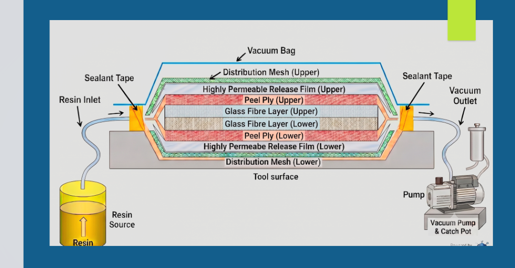
A complete cross-sectional breakdown of the dry stack setup: tool surface, lower/upper distribution mesh, highly permeable release film, peel ply, biaxial glass fiber plies, sealed vacuum bag, and vacuum catch pot.
Procedural Sequence & Parameters
- Surface Prep & Release: Mold wiped meticulously with acetone to strip contaminants, followed by uniform application of NC55 release agent for clean demolding without surface tearing.
- Symmetrical Dry Layup: Stacking sequence composed of bottom distribution mesh, permeable release film, peel ply, 4 physical layers of bi-directional glass fiber (~800 GSM), top peel ply, release film, and top distribution mesh.
- Vacuum Bagging & Integrity Drop Test: Sealed hermetically with specialized sealant tape and high-elongation vacuum film. A pressure drop test was conducted to ensure a 100% leak-free boundary prior to resin introduction.
- Resin System Formulation: Prime 37 Epoxy paired with Ampreg 3X Hardener, precisely mixed at the calibrated 100:29 weight ratio (total calculated mix: 258g including 72g consumable hose buffer).
- Vacuum Degassing & Infusion: Mixed resin degassed inside a vacuum chamber for 5 minutes to purge entrapped micro-air bubbles, then drawn continuously through the dry laminate via atmospheric pressure.
Compression Testing: Balsa Wood vs. PET Foam (ISO 844)
Destructive compressive mechanical testing was carried out according to the ISO 844 international standard to benchmark the structural load carrying capacity of end-grain balsa wood core against recycled engineered thermoplastic PET foam planks.
Empirical stress-strain curves comparing epoxy-infused Balsa 150 against PET Plank 100 under uniaxial compressive loading.
Mechanism Insight: The balsa wood exhibits continuous cellular shear stiffening, whereas PET foam experiences elastic cell-wall bending followed by cell collapse plateau before densification.
Compressive Test Findings
- 12× Strength Differential: Infused Balsa 150 demonstrated a dramatic 12-fold superiority in compressive yield stress over the standard PET Plank 100 foam.
- High Shear Stiffness: The natural axial cellular orientation of end-grain balsa provides outstanding shear transmission between composite face skins in sandwich panels, critical for wind turbine blade shear webs.
- Application Trade-off: While PET foam delivers significant weight reduction, thermoformability, and recyclability (Kerdyn Green), balsa wood remains indispensable for localized regions experiencing concentrated compressive and shear stresses.
Tensile Performance: Balsa Wood (ASTM C297)
Flatwise tensile testing performed on a Zwick/Roell universal material testing machine to measure the ultimate tensile strength and Young's modulus of balsa wood core specimens under perpendicular tension.
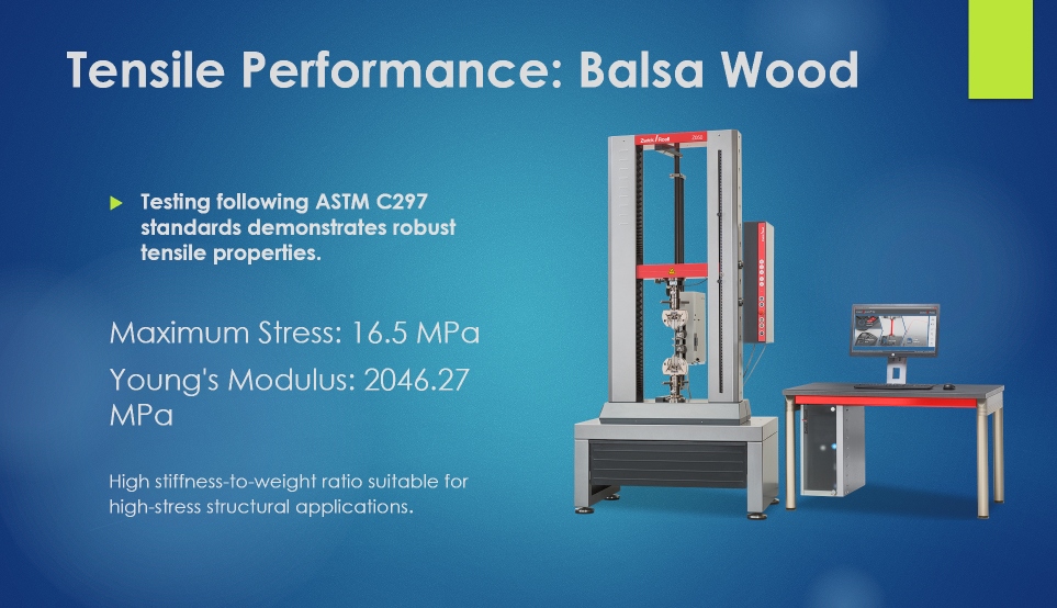
Dual-column high-precision hydraulic tensile testing frame with digital extensometer and real-time load cell acquisition used to evaluate coupon failure thresholds.
ASTM C297 Tensile Metrics
- Ultimate Tensile Stress: Specimens withstood maximum tensile stress of 16.5 MPa prior to catastrophic cell wall rupture.
- Elastic Modulus (Stiffness): Recorded an exceptionally high elastic tensile modulus of 2,046.27 MPa, validating its superior resistance to elongation under high operational loads.
- Validation Against Aerodynamic Fatigue: Wind turbine blades must endure 20 to 30 years of continuous cyclical gusts, moisture, and temperature fluctuations. Destructive tensile coupon testing ensures the resin-impregnated core prevents skin-core debonding under extreme aerodynamic lift forces.
Simulation Of the Laminate (SolidWorks FEA)
Finite Element Analysis (FEA) modeling conducted in SolidWorks Simulation to computationally validate the stress distribution and deflection behavior of a custom 8-ply balanced biaxial glass fiber composite laminate shell.
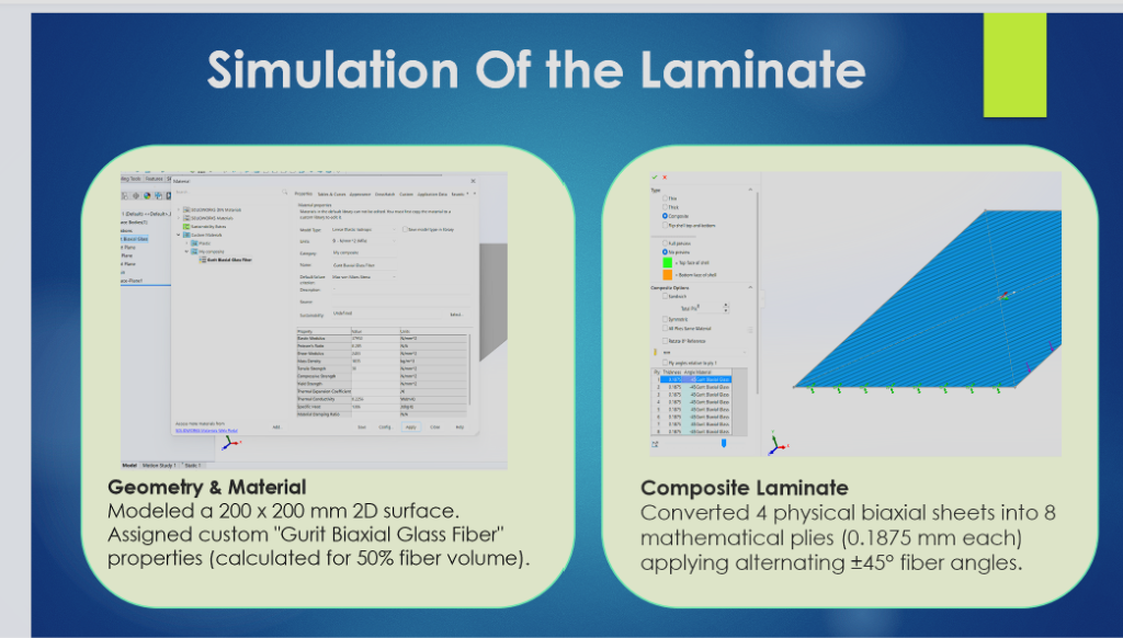
Geometry & Plies: 200 mm × 200 mm 2D shell surface. Converted 4 physical biaxial sheets into 8 discrete mathematical plies (0.1875 mm thickness each) with alternating ±45° fiber angles and 50% fiber volume fraction.
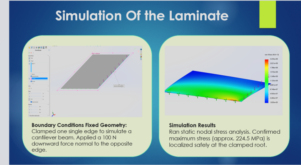
Cantilever Loading: Clamped one edge (fixed support) and applied a 100 N downward edge load. Static nodal stress confirmed maximum Von Mises stress of 224.5 MPa safely localized at the clamped root.
Simulation Architecture & Correlation
Design Conclusion: The 8-ply balanced ±45° laminate architecture distributes cantilever shear and bending moments with high symmetry, preventing out-of-plane warping and ensuring that maximum stress concentrations are contained well below the ultimate tensile strength of Gurit biaxial glass fiber systems.
Download Full Presentation Deck
Access the complete 25-slide presentation on "Fiber Reinforced Composites" covering PET foam extrusion, sandwich panel mechanics, VARTM sequence, and laboratory test datasets.
Download Slides (PDF, 2.7 MB)